Projects

Top 7 Best Arduino Robot Kits for Beginners: 2024 Reviews

Explore the top Arduino starter kits for beginners with detailed reviews and a comprehensive buyer’s guide. Start your journey into electronics today!
Arduino robot kit assembled on a breadboard with LCD and 9-V battery

Arduino Robot kits are a one-stop solution for newbies, hobbyists, and engineers to be familiar with the Robotics and Arduino. It is a great technical platform to start and build mobile robots with a great sense of creativity.

To perform such tasks, you must get all the necessary parts from different sources which is a bit complicated. A solution to this is to pay for Arduino robot kit and get them with less effort for designing cool projects. A good robot kit comes with clear instructions, support and saves Your time and money.

There are many Arduino robot kits on the market today; each has its unique hardware devices and specifications. As it is very difficult to decide the right one, We made a case study on different Arduino robot kits and presented you the best 7 Arduino robot kits that offer various components, cost, project details, source code and many more.


List of the Best Arduino kits for beginners

1. Elegoo Project Smart Robot Car Kit 

ELEGOO UNO R3

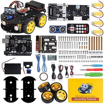
First on our list is the ELEGOO UNO R3 smart robot car kit. This is a robocar kit that is Arduino compatible and made specifically for beginners and pro electronic enthusiast kids and adults.

With an easy to follow tutorial for assembling it, this STEM educational kit teaches programming and robotics to kids with ease.

It comes in a 24 module package and is an integrated solution for robotics learning. The modules include Infrared remote control, obstacle avoidance, Tracking and mobile control as well. These are both for the Android and iOS operating systems.

Elegoo has a BLE tool app which gives you control over the kit using your mobile. It has an HC-08 module which is easy to use. The manual CD will give you a tutorial on how to use it as well. It has HD Videos of the tutorials, rendering and assembly of the car along with programming education for the car as well.

Very easy to assemble, the interface of the module has been modified with an XH2.54 port which makes the assembly much easier and removes any chance of any errors.

The car has a rechargeable battery and an overall minimal design. A great gift for budding learners of the age 12 or above. The robot car comes with a 1-year manufacturer’s warranty from the date of purchase.

Compatible Age groups: 12 years or above

Things we liked about the kit:

  • STEM educational robot car kit
  • Has a detailed tutorial CD
  • 24 Modules for easy assembly
  • Intelligent obstacle avoidance
  • Line tracking
  • Elegoo BLE Tool Mobile App
  • Rechargeable Battery
  • 1 Year warranty

Things we didn’t like about it:

  • None too specific to mention

Buy Now From Amazon

2. Makeblock Educational Robot Kit

makeblock kit

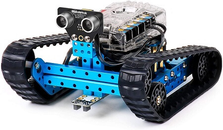
Next up, we have the Makeblock mBot STEM robot kit. An advanced version with updates than its predecessor, this one comes with transformational features such as a 3 in one robot.

It can be coded with a variety of functions and this makes it a fun tool to learn to code for kids. It can be built in just a few hours that is as simple as assembling building blocks. While it may be advertised as it will take about 45 minutes, it might end up taking a few hours to build it.

Makeblock has a signature Me Auriga Board that is compatible with the Arduino Mega 2560. The Arduino IDE can be used for development and the building guide that comes with the robot aids in this as well.

With proper personalization, the robot lets you add unique features to it and special build models such as a bird, raptor or a land raider too.

To run it, you will need 6 AA batteries. While there is no warranty, you can write to their customer support for any queries and issues support@makeblock.com

Compatible Age Groups: 10+ years of age

Things we liked about it:

  • An advanced Arduino model
  • Block-based building
  • 3 in one model
  • Uses the Me Auriga Board that is compatible with the Arduino Mega 2560

Things we didn’t like about it:

  • Has No warranty
  • As it does not have a dedicated interface, you will be forced to use the Arduino Mega 2560 IDE for development

Buy Now From Amazon

3. Ubtech Jimu Robot Astrobot Series: Cosmos Kit 

ubtech kit

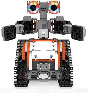
Next up, we have UBTECH JIMU Astrobot Robot series. This cosmos kit is enabled by a mobile app and teaches kids to build and code through STEM Learning.

With over 384 parts, connectors and fasteners, the robot has a total of 5 servo motors, 2 LED lights and a central control box. The battery has a USB based charger. The sensor that comes can be connected to the Bluetooth speaker and can amplify your reach and capability to use the robot more.

Blockly’s unique coding platform teaches you to learn to code very easily and better. You can program your robot to be able to pick stuff, navigate obstacles, control the light settings, create sound effects, develop a unique personality and much more.

With the Brickly coding challenges, you can test your skills against others and also slowly learn to create and write better code. The 360 Degrees 3D animated building instruction will further aid in developing a better model.


The robot can be programmed for custom actions with the Pose, Record Play function or the PRP function. With a total of 387 snap-together parts in it, it is truly a fun play piece. The free app works both on Android and iOS devices.

The winner of the Tillywig 2018 brainchild award AND the CES 2017 innovation awards honoree, the robot also won the Time to Play magazine’s 2016 most wanted list and the IFA awards for 2015 best of show. Thoroughly highly rated and reviewed, as it is primarily a toy, there is no warranty to it

Compatible Age Groups: 8 to 12 years of age

Things we liked about it:

  • STEM learning robot kit
  • 360 degrees animated building instruction
  • 387 snap together pieces
  • The app allows for easier learning to code and play
  • Award-winning design
  • Sensors and a Bluetooth speaker embedded too
  • The PRP function is truly revolutionary

Things we didn’t like about it:

  • No warranty

Buy Now From Amazon

4. Osoyoo Robot Car Starter Kit 

osyoo kit

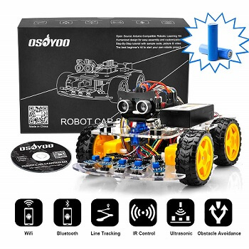
OSOYOO’s robot car kit is a DIY robot that is made on the Arduino UNO R3 chipset. This lets you control the robot from both using Android and iOS app as well. High in quality, the robot comes with a wide range of functions and is one of the affordable and budget-friendly models in our list.

This kit can be modelled into a robot with WiFi controlled driving or even a battle bot as well. You can also program it for imitation driving as well. The DIY robot can also perform line tracking, detect and avoid collisions with obstacles and much more.

Perfect for beginners and pros alike, the detailed tutorial that comes with the kit will help you get started with it and become a pro as well on it. Kids can easily learn to code, the basics of IoT (Internet of Things), electronics, robotics and much more.

It can also be controlled using an Infrared remote control that is included in the box. The kit comes with two 9 volt batteries which are based out of rechargeable lithium-ion. The charger box lets you charge it. It also includes all the accessories needed for building it further.

Compatible age groups: 10+ years

Things we liked about the kit:

  • Highly affordable and easy to build a DIY Robot kit
  • High-Quality UNO R4 Arduino board
  • Beginner-friendly yet pro built
  • Detailed tutorial included in it
  • Can imitate drive, automatic drive and much more.
  • Can detect and avoid obstacles, line track and object motion follow as well.
  • IR Control remote also available
  • Can also be controlled using the WiFi and a smartphone
  • Two 9 volt rechargeable batteries included

Things we didn’t like about it:

  • No warranty

Buy Now From Amazon

5. Lewansoul Robotic Arm Kit 

LewanSoul 6DOF

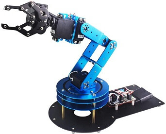
Next up, we have a Robotic Arm kit rather than a movable entire robot. The LewanSoul 6DOF is a robotic arm kit based out of an Arduino. This is also a STEM-based robot learning kit that comes with app control and a tutorial as well.

A highly mechanical and minute detailed kit, the arm uses a high precision digital servo that increases the accuracy of the robot’s control.

LeArm has detailed video tutorials on how to use the robotic arm and there is also detailed 3D videos available for setting it up as well.

Entirely made out of metal, the robot arm is highly durable in nature..the metal mechanical claw is made out of durable aluminium brackets and the bottom plate is also pure metal.

The structural design of the robot arm is made for a greater freedom of movement and this  let’s it grab any object with greater grip and move it in any direction possible.

The robot can be easily controlled using the Android or the iOS app and also through the Graphical PC software as well.

It has a 5axis rotation, a very cool surface design and greater grip and movement making it a great guy for both beginners and pro level enthusiasts.

Compatible Age Groups: 8 Year and above

Things we liked about it:

  • Highly precise movement and high quality budget friendly robotic arm
  • Can move about in 5 axis breadth
  • Has a detailed tutorial for design and using it.
  • Can perform various operations from.simple holding to moving and also be programmed for complex actions as well.
  • Can be controlled using the mobile app (both Android and iPS) or the PC software.

Things we didn’t like about it:

  • No warranty
  • Batteries not included
  • Only a single part of movement on a single place; no wheels

Buy Now From Amazon

6. Elegoo Penguin Bot Biped Robot Kit 

elegoo kit

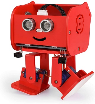
Yet another ELEGOO Robot Arduino kit on our list, the Penguin bot, as the name says, when assembled, looks like a penguin robot. The Bot Biped robot kit is a STEM learning kit for beginner kids and hobbyist adults as well.

Based on the DIY Arduino platform, the ELEGOO penguin bot comes with the promise of quality of the ELEGOO and its reviews and ratings are high as well.

Coming to the actual bot, it has great features such as auto-follow, Music player and dancing as well. It can follow a single line, can detect and avoid obstacles and can also be controlled using an IR remote as well. Using the Bluetooth APP, you can control the robot to sing, dance and move from a point to another.

Available not just in red colour, the bot is also available in black and transparent colours as well. The headcovers or head masks are available in 6 delicate designs to make it more personalized as it gets.

With the easy to follow tutorials, your kid can learn to code, program and do much more with robots and have hands-on experience while doing so. This tutorial CD comes enclosed in the kit of the robot.


Perfect for kids above the age of 10, even adults can find fun assembling and using the robot. The pack comes included with the Servo motors, parts and the containers and everything needed to assemble and use the robot. The kit includes a magnetic screwdriver and a few extra spare parts as well.

Compatible age groups: 10+ years

Things we liked about the kit:

  • Easy to build STEM Learning ROBOT kit
  • Highly reviewed and rated
  • Can auto-follow, sing, dance and through the speaker, also mimic singing and avoid obstacles as well
  • Can also be controlled using the Bluetooth App as well
  • Comes with 6 extra delicate design face covers for added personalization
  • The tutorial CD teaches coding at a basic level extensively
  • Includes extra parts and a magnetic screwdriver as well

Things we didn’t like about it:

  • No warranty
  • No advanced customizations available

Buy Now From Amazon

7. Freenove Quadruped Robot Kit 

freenove kit

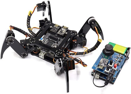
The Freenove Quadruped Robot has a very cool design to it. Made out of the evergreen Arduino Raspberry Pi Processing board, the robot has a Spider-like feature to it and can crawl about the surface rather than just roll on wheels.

This kind of movement by the robot makes it one of a kind and very interesting to code and program from scratch. All you need to do is follow a simple step by step tutorial that will help you in assembling and coding the robot to work.

The robot can be controlled using a wireless remote control. This remote comes in pieces in the package and you will be building it as well. It can also be controlled using a PC software or using an Android phone as well.

Freenove gives you the necessary code library to let you reprogram the robot. This, with the extra free ports that are available to the robot, gives you the ability to connect to other modules, circuits and re-purpose the robot to your creative and imaginative extent.

The package is complete with not just the parts but also additional magnetic screwdrivers and spanners required to get the job done.

Compatible Age Groups: 13 Years and above

Things we liked about it:

  • A unique model that walks on 4 legs (quadrapod) rather than moving on wheels
  • Easy to build and code using the step by step tutorials
  • Can be controlled using a computer, a mobile app or a wireless remote
  • The remote comes in the package and is part of the DIY process
  • Package comes with magnetic screwdrivers and spanners for fixing and building it
  • Can be reprogrammed and repurposed as well

Things we didn’t like about it:

  • No warranty

Buy Now From Amazon

Buying Guide for Arduino Robot Kits

One must consider the following factors before choosing the Arduino robot kits that satisfy their requirements. Read on to know more about them…

 1. Price

Price is the most important factor you should look into when you decide to purchase the Arduino robot kits. One must go with the price that he can afford. Also, check for the best features that the branded product offers.

If you are not willing to spend more amount then go for mid-range products that are given in the article.

 2. Smart navigation

Nowadays all the electronic devices are equipped with the smart navigation feature. Without this feature, no manufacturer is releasing the product in the market. It has become very important because you can simply control the device with single touch even at your busy times.

When you turn ON the smart navigation mode, it automatically starts moving in left-right, front-back directions. It can even crawl and jump sometimes to avoid the obstacles using the smart technology feature.

If you wish to opt for this amazing feature then you need to pay extra dollars. Take a wise decision before you make a purchase.

 3. Easy accessing

So far you have considered only the price and smart navigation option. But the 3rd essential factor is easy accessing. For instance, you have purchased a product and unable to handle it or don’t know how to assemble the robot kit then its totally waste of your coin.

My best suggestion for you is whenever you decide to purchase any gadget get complete idea about it and then make a plan.

If you wish for an item and doesn’t know how to use then it doesn’t make a sense.

4. List of components

When you heard about the list of components, it may be wired or funny. Trust me you should also check for the number of components provided in the kit. Because sometimes the kit may not have all the necessary components required for a project.

The other reason is heavyweight, some of them do not like to carry heavy weighted items. There is also a misconception that heavy weighted items do not offer high performance. But its totally false and you may not be satisfied also.

Make sure you check the list of components offered in the robot kit and purchase the best one that matches your requirements.

Arduino FAQs

Arduino is an open-source electronics platform based on easy-to-use hardware and software. It's intended for anyone making interactive projects.

Key aspects of Arduino include:

  • Hardware: Arduino boards are microcontrollers (essentially small computers) that can read inputs (like light on a sensor, a finger on a button, or a Twitter message) and turn them into outputs (activating a motor, turning on an LED, publishing something online).
  • Software: The Arduino IDE (Integrated Development Environment) is a free software that runs on your computer, used to write and upload code to the Arduino board. The programming language is based on C/C++.
  • Community: A large and active global community supports Arduino, sharing projects, code, and solutions.
  • Open Source: Both the hardware designs and software are open-source, allowing anyone to modify and distribute them.

Arduino is popular among hobbyists, artists, designers, and engineers for its simplicity, affordability, and versatility in creating a wide range of electronic projects, from simple blinking LEDs to complex robots and IoT devices.

The Arduino Uno is the most popular and widely used Arduino board. It's often recommended for beginners due to its robust design and extensive documentation.

Key features of the Arduino Uno include:

  • Microcontroller: Typically uses the ATmega328P microcontroller.
  • Digital Pins: 14 digital input/output pins (6 of which can be used as PWM outputs).
  • Analog Pins: 6 analog input pins.
  • Connectivity: USB port for programming and power, DC power jack.
  • Memory: 32KB of flash memory (for storing code), 2KB of SRAM, and 1KB of EEPROM.
  • Operating Voltage: 5V.

The Uno is versatile enough for a wide range of projects, from simple sensor readings to controlling motors and displays. Its standard form factor also means it's compatible with a vast number of "shields" (add-on boards that provide extra functionality like Ethernet, motor control, or LCD screens).

The Arduino Uno has a total of 20 general-purpose input/output (GPIO) pins available for users, broken down as follows:

  • 14 Digital Pins: Labeled 0 to 13. These can be used as either inputs or outputs.
    • Pins 0 (RX) and 1 (TX) are also used for serial communication.
    • 6 of these digital pins (typically 3, 5, 6, 9, 10, 11) support Pulse Width Modulation (PWM), indicated by a tilde (~) symbol next to the pin number on the board.
  • 6 Analog Input Pins: Labeled A0 to A5. These pins can read analog voltages (typically 0-5V) and convert them into a digital value (0-1023). They can also be used as digital I/O pins if needed.

In addition to these GPIO pins, the Arduino Uno also has pins for power (3.3V, 5V, GND, VIN), a reset pin, and IOREF pin.

An Arduino board is a type of microcontroller development board. It's a physical circuit board that includes a microcontroller (a small, self-contained computer on a single chip) and other components necessary to program and interface with it easily.

Key characteristics of an Arduino board:

  • Microcontroller: The "brain" of the board, which executes the code you write. Different Arduino boards use different microcontrollers (e.g., ATmega328P on the Uno, SAMD21 on some newer boards).
  • Input/Output (I/O) Pins: These allow the microcontroller to interact with the physical world. You can connect sensors, buttons, LEDs, motors, and other electronic components to these pins.
  • Power Supply Circuitry: Manages power to the board, often allowing it to be powered via USB or an external power supply.
  • Programming Interface: Usually a USB port that allows you to connect the board to a computer to upload programs (called "sketches").
  • Supporting Components: Oscillators for timing, voltage regulators, LEDs for status indication, reset button, etc.

Arduino boards are designed to be user-friendly, making it easier for beginners to get started with electronics and programming. They are part of the larger Arduino open-source ecosystem, which includes the Arduino IDE (software) and a vast online community.

The Arduino IDE (Integrated Development Environment) is a free, open-source software application used to write, compile, and upload code (called "sketches") to Arduino-compatible microcontroller boards.

Key features of the Arduino IDE:

  • Cross-Platform: It runs on Windows, macOS, and Linux operating systems.
  • Code Editor: A simple text editor with syntax highlighting for writing Arduino code (which is based on C/C++).
  • Compiler: Converts the human-readable code into machine code that the microcontroller on the Arduino board can understand and execute.
  • Uploader: Transfers the compiled code from your computer to the Arduino board via a USB connection.
  • Serial Monitor: A built-in tool that allows for two-way communication between the Arduino board and the computer. Useful for debugging and displaying data from sensors.
  • Library Manager: Allows you to easily find, install, and manage libraries (pre-written code packages that extend Arduino's functionality for specific tasks or hardware).
  • Board Manager: Allows you to install support for various Arduino boards and other compatible third-party boards.

The Arduino IDE is designed to be relatively simple and easy to learn, making it accessible for beginners in programming and electronics.

Coding for Arduino involves writing programs (called "sketches") in a language based on C/C++ and using the Arduino IDE to upload them to an Arduino board.

Here's a general process:

  1. Install the Arduino IDE: Download it from the official Arduino website (arduino.cc) and install it on your computer.
  2. Connect your Arduino board: Use a USB cable to connect your Arduino board to your computer.
  3. Configure the IDE:
    • Select your board type (e.g., Arduino Uno) from the "Tools > Board" menu.
    • Select the correct serial port (the one your Arduino is connected to) from the "Tools > Port" menu.
  4. Write your code (sketch):

    Arduino sketches have a basic structure:

    // This code runs once when the sketch starts
    void setup() {
      // Initialize pins, libraries, serial communication, etc.
      pinMode(LED_BUILTIN, OUTPUT); // Example: Set the built-in LED pin as an output
    }
    
    // This code runs repeatedly in a loop
    void loop() {
      // Main logic of your program
      digitalWrite(LED_BUILTIN, HIGH); // Turn the LED on
      delay(1000);                     // Wait for a second
      digitalWrite(LED_BUILTIN, LOW);  // Turn the LED off
      delay(1000);                     // Wait for a second
    }

    You'll use Arduino-specific functions (like pinMode(), digitalWrite(), analogRead()) and standard C/C++ syntax.

  5. Verify/Compile your code: Click the "Verify" button (checkmark icon) in the IDE. This checks your code for syntax errors and compiles it.
  6. Upload your code: If verification is successful, click the "Upload" button (right arrow icon). This sends the compiled code to your Arduino board.
  7. Test: Observe your Arduino board to see if the code works as expected. You can use the Serial Monitor for debugging if needed.

Learning involves understanding basic programming concepts (variables, loops, conditions), Arduino-specific functions, and how to interface with electronic components.

Programming an Arduino is essentially the same as "coding an Arduino." It refers to the process of creating a set of instructions (a program or "sketch") that tells the Arduino board what to do, and then transferring that program to the board's microcontroller.

The steps are identical to those for coding an Arduino:

  1. Get the Arduino IDE: Download and install the official Arduino Integrated Development Environment.
  2. Connect Hardware: Connect your Arduino board to your computer via USB.
  3. IDE Setup: In the Arduino IDE, select the correct board type (e.g., "Arduino Uno") under "Tools > Board" and the correct COM port under "Tools > Port."
  4. Write the Program (Sketch):

    Arduino programs are written in a simplified version of C/C++. Every sketch must contain two main functions:

    • void setup() { ... }: This function runs once when the Arduino board is powered on or reset. It's used for initial configurations, like setting pin modes or starting serial communication.
    • void loop() { ... }: After setup() finishes, this function runs continuously in a loop as long as the board is powered. This is where the main logic of your project resides.
  5. Compile (Verify): Click the "Verify" button (checkmark icon) in the IDE. This checks your code for errors and converts it into a format the Arduino can understand.
  6. Upload: Click the "Upload" button (right-arrow icon). This transfers the compiled program to the Arduino board's memory.
  7. Observe and Debug: Check if your project behaves as intended. Use the Serial Monitor (Tools > Serial Monitor) for debugging by printing values or messages from your Arduino.

To learn programming for Arduino, you'll need to understand basic C/C++ syntax, Arduino-specific functions and libraries, and how to interact with electronic components like sensors and actuators.

In the context of the Internet of Things (IoT), Arduino plays a significant role as a hardware platform for creating connected devices. IoT refers to the network of physical objects ("things") embedded with sensors, software, and other technologies for the purpose of connecting and exchanging data with other devices and systems over the internet.

Here's how Arduino fits into IoT:

  • Sensing and Actuation: Arduino boards can easily interface with a wide variety of sensors (temperature, humidity, motion, light, etc.) to collect data from the environment. They can also control actuators (motors, lights, relays) to perform actions based on this data or commands received.
  • Connectivity: While basic Arduino boards like the Uno don't have built-in internet connectivity, they can be easily paired with "shields" or modules that provide Wi-Fi (e.g., ESP8266, ESP32 based modules), Ethernet, Bluetooth, LoRa, or cellular connectivity. Some Arduino boards (like the Arduino MKR series or ESP32-based boards programmed via Arduino IDE) come with these capabilities built-in.
  • Prototyping: Arduino's ease of use and affordability make it an excellent tool for rapidly prototyping IoT devices and applications.
  • Data Processing: Arduino can perform basic data processing locally before sending it to the cloud or another device.
  • Gateway to the Cloud: Arduino-based devices can send sensor data to cloud platforms (like AWS IoT, Google Cloud IoT, Microsoft Azure IoT, Blynk, Thingspeak) for storage, analysis, and visualization. They can also receive commands from these platforms.

Examples of Arduino in IoT: Smart home devices (controlling lights/appliances), environmental monitoring systems, agricultural sensors, health monitoring devices, industrial control systems, and more.

Arduino, often in conjunction with more powerful single-board computers like Raspberry Pi or dedicated IoT modules like ESP32, provides an accessible entry point for building the "things" in the Internet of Things.

"Arduino Uno MCQ" refers to Multiple Choice Questions related to the Arduino Uno board and its ecosystem. These questions are often used in quizzes, exams, or learning materials to test knowledge about various aspects of the Arduino Uno.

Topics covered by Arduino Uno MCQs might include:

  • Hardware Specifications: Microcontroller type (ATmega328P), number of digital/analog pins, memory (Flash, SRAM, EEPROM), operating voltage, clock speed.
  • Pin Functions: Digital I/O, analog input, PWM, serial communication (TX/RX), SPI, I2C.
  • Arduino IDE: Basic functions, compiling, uploading, serial monitor.
  • Programming Concepts: Structure of an Arduino sketch (setup(), loop()), common functions (pinMode(), digitalWrite(), analogRead(), delay()), variables, data types, control structures (if, for, while).
  • Basic Electronics: Connecting LEDs, resistors, buttons, sensors.
  • Powering the Uno: USB power, VIN, barrel jack.

Example MCQ:

Which microcontroller is used in the Arduino Uno R3?

  1. ATmega2560
  2. ATmega328P
  3. ESP32
  4. SAMD21

Correct Answer: B) ATmega328P

These MCQs help learners assess their understanding and prepare for more advanced topics or practical applications involving the Arduino Uno.

The primary microcontroller used in the most common version of the Arduino Uno (like the Arduino Uno R3) is the ATmega328P.

Key details about the ATmega328P:

  • Manufacturer: Microchip Technology (formerly Atmel).
  • Architecture: 8-bit AVR RISC-based microcontroller.
  • Clock Speed: Typically runs at 16 MHz on the Arduino Uno.
  • Flash Memory: 32 KB (of which 0.5 KB is used by the bootloader). This is where your Arduino sketch is stored.
  • SRAM: 2 KB. This is used for storing variables while your sketch is running.
  • EEPROM: 1 KB. This is non-volatile memory that can be used to store data that needs to persist even when the board is powered off.
  • Digital I/O Pins: Provides the digital pins available on the Uno.
  • Analog-to-Digital Converter (ADC): Provides the analog input capabilities.

The ATmega328P is a popular and well-documented microcontroller, which contributes to the Arduino Uno's ease of use and extensive community support.

There are many types of Arduino boards, each designed with different features, capabilities, form factors, and intended applications. It's difficult to give an exact number as new official boards are released, older ones are retired, and there's a vast ecosystem of third-party "Arduino-compatible" boards.

However, official Arduino boards can be broadly categorized:

  • Entry Level / Basic Boards:
    • Arduino Uno: The most popular, great for beginners.
    • Arduino Nano: Small, breadboard-friendly version of the Uno.
    • Arduino Micro: Similar to Nano, but with built-in USB communication (ATmega32U4).
    • Arduino Leonardo: Uses ATmega32U4, can act as a USB HID (keyboard/mouse).
  • Enhanced Features / More Powerful Boards:
    • Arduino Mega 2560: More I/O pins, more memory, for larger projects.
    • Arduino Due: 32-bit ARM Cortex-M3 microcontroller, faster, more memory, 3.3V logic.
  • IoT Focused Boards:
    • Arduino MKR Series (e.g., MKR WiFi 1010, MKR GSM 1400, MKR NB 1500, MKR WAN 1310): Designed for IoT applications with built-in connectivity options (Wi-Fi, GSM, NB-IoT, LoRa).
    • Arduino Nano 33 IoT: Small form factor with Wi-Fi/Bluetooth and a crypto chip.
  • Education Focused Boards:
    • Boards included in specific educational kits like the Arduino Starter Kit or Arduino Education kits.
  • Tiny Form Factor Boards:
    • Arduino Nano Every: An updated version of the Nano.
    • Various smaller boards for wearables or compact projects.
  • Professional / Advanced Boards:
    • Portenta Family (e.g., Portenta H7): High-performance boards for industrial applications, AI, and machine learning.

Beyond official Arduino boards, there are countless clones and derivatives made by other manufacturers, often offering different features or price points. The Arduino software (IDE) also supports many of these third-party boards (like ESP32 and ESP8266 based boards).

So, while there isn't a fixed number, you can say there are dozens of official Arduino board types and hundreds, if not thousands, of compatible boards in the broader ecosystem.

As mentioned previously, there isn't a single, definitive number for how many types of Arduinos exist. The Arduino platform is open-source, which has led to a wide variety of boards being developed both by Arduino (the official organization) and by third-party manufacturers.

We can categorize them to understand the diversity:

  1. Official Arduino Boards: These are designed and sold by Arduino.cc. The number fluctuates as new boards are introduced and older ones are phased out. Key families include:
    • Classic Boards: Uno, Leonardo, Mega, Nano, Micro.
    • IoT Boards: MKR series (WiFi, GSM, NB-IoT, LoRa, Vidor), Nano 33 IoT, Portenta.
    • Education Boards: Boards specifically designed for educational kits.
    • Advanced Boards: Due, Zero, Portenta H7.

    You can find the current official lineup on the Arduino website. There are typically a few dozen distinct official models available at any given time.

  2. Arduino-Compatible Boards (Clones and Derivatives): These are boards made by other companies that are designed to be functionally similar to official Arduino boards and can be programmed using the Arduino IDE. There are hundreds, possibly thousands, of these, ranging from direct clones to boards with significantly different features (e.g., ESP8266 and ESP32 based boards, which are very popular and often programmed using the Arduino IDE).

So, if you're asking about official Arduino boards, there are several dozen distinct types. If you include all Arduino-programmable boards, the number is much, much larger and constantly growing.

Resetting an Arduino Uno restarts the program (sketch) currently loaded on its microcontroller from the beginning. It's similar to restarting a computer program. There are several ways to reset an Arduino Uno:

  1. Physical Reset Button:
    • Most Arduino Uno boards have a small, physical pushbutton on the board, usually located near the USB connector or the edge of the board.
    • Simply pressing and releasing this button will reset the microcontroller.
  2. Software Reset (via code):
    • You can trigger a reset from within your Arduino sketch. This is less common for a simple reset but can be useful in certain applications.
    • One way is to call a function that jumps to address 0: void(*resetFunc)(void) = 0; resetFunc();
    • Caution: Use software resets carefully, as an improperly implemented one could lead to a continuous reset loop.
  3. Reset via the Reset Pin:
    • The Arduino Uno has a "RESET" pin. Bringing this pin LOW (to Ground) momentarily will reset the microcontroller.
    • This is often used by shields or external circuitry to control the reset state of the Arduino. For example, you could connect a button between the RESET pin and GND.
  4. Reset during Upload:
    • When you upload a new sketch to the Arduino Uno via the USB connection, the Arduino IDE (or the underlying `avrdude` programmer) often triggers a reset automatically. This is typically managed by the DTR (Data Terminal Ready) signal from the USB-to-serial chip on the Uno, which is connected to the microcontroller's reset line via a capacitor.
  5. Power Cycle:
    • Disconnecting the power supply (USB cable or external power) and then reconnecting it will also cause the Arduino Uno to reset and start its program from the beginning.

The most common and straightforward method for users is the physical reset button on the board.

The Arduino Nano is a small, complete, and breadboard-friendly development board based on the ATmega328P microcontroller (the same one used in the Arduino Uno R3) or the ATmega168 (in older versions).

Key features and characteristics of the Arduino Nano:

  • Compact Size: Its main advantage is its small footprint (approximately 1.70" x 0.73" or 43mm x 18mm), making it ideal for projects where space is limited, such as wearables, embedded systems, or compact prototypes.
  • Breadboard-Friendly: It has pin headers that allow it to be easily plugged directly into a breadboard for prototyping.
  • Functionality: It offers similar functionality to the Arduino Uno.
    • Microcontroller: ATmega328P (common versions) or ATmega168.
    • Digital I/O Pins: 14 (6 provide PWM output).
    • Analog Input Pins: 8 (A0-A7), which is two more than the Uno's A0-A5. Pins A6 and A7 are analog input only.
    • Memory: Same as Uno (32KB Flash, 2KB SRAM, 1KB EEPROM for ATmega328P versions).
    • Operating Voltage: 5V.
  • Connectivity:
    • USB: Typically uses a Mini-B USB connector for programming and power (some newer "Nano Every" or clones might use Micro-USB or USB-C).
    • It lacks a DC power jack; power is usually supplied via USB or the VIN pin.
  • Cost-Effective: Often more affordable than the Arduino Uno.

The Arduino Nano is a popular choice for projects that require the capabilities of an Uno but in a much smaller package. It's programmed using the Arduino IDE, just like other Arduino boards.

There are also newer versions like the "Arduino Nano Every" which uses an ATmega4809 microcontroller, and the "Arduino Nano 33" series (e.g., Nano 33 IoT, Nano 33 BLE Sense) which use more powerful 32-bit ARM microcontrollers and often include built-in wireless connectivity, operating at 3.3V.

Arduino is an incredibly versatile platform used for a vast range of applications, primarily in creating interactive electronic projects. Its ease of use, affordability, and open-source nature make it popular among hobbyists, students, artists, designers, and engineers.

Here are some common uses and application areas for Arduino:

  • Education: Teaching programming, electronics, and robotics fundamentals.
  • Prototyping: Rapidly developing and testing ideas for new electronic products and systems.
  • DIY Electronics and Hobby Projects:
    • Home automation (controlling lights, appliances, thermostats).
    • Robotics (building and controlling robots of various complexities).
    • Wearable technology (e.g., custom smartwatches, interactive clothing).
    • Art installations and interactive art.
    • Musical instruments and sound projects.
    • Custom game controllers.
  • Internet of Things (IoT):
    • Creating sensor nodes that collect data and send it to the internet.
    • Developing smart devices that can be controlled remotely.
    • Environmental monitoring (temperature, humidity, air quality).
  • Automation:
    • Automating repetitive tasks in homes, labs, or small-scale industrial settings.
    • Controlling motors, pumps, and other actuators.
  • Data Logging: Collecting and storing data from sensors over time.
  • Scientific Instruments: Building custom, low-cost measurement and data acquisition tools for experiments.
  • Accessibility Projects: Creating assistive devices for people with disabilities.
  • Small-Scale Manufacturing and Customization: Building custom control systems for specific needs.

Essentially, if you can imagine a project that involves reading sensors and controlling outputs, there's a good chance Arduino can be used to build it, especially at a prototype or small-scale level.

The microcontroller predominantly used in the Arduino Uno, particularly the popular R3 version, is the ATmega328P.

This is an 8-bit AVR microcontroller manufactured by Microchip Technology (formerly Atmel). It features:

  • 32KB of ISP flash memory (0.5KB used for the bootloader)
  • 2KB of SRAM
  • 1KB of EEPROM
  • Operates at a clock speed of 16 MHz on the Uno.

The ATmega328P is responsible for executing the code (sketch) that you upload to the Arduino Uno, controlling its input/output pins, and managing its various functionalities.

The Arduino Uno has 6 analog input pins.

These pins are labeled A0, A1, A2, A3, A4, and A5 on the board.

Key features of these analog pins:

  • Function: They are primarily used to read analog voltages, typically from sensors that output a varying voltage (e.g., temperature sensors, potentiometers, light sensors).
  • Resolution: The Arduino Uno has a 10-bit Analog-to-Digital Converter (ADC). This means it can map input voltages between 0 and 5 volts (the operating voltage) into integer values between 0 and 1023.
  • Dual Use: These pins can also be configured and used as digital input/output pins if needed, just like the regular digital pins (0-13). When used as digital pins, A0 corresponds to digital pin 14, A1 to digital pin 15, and so on.

When people ask about the number of "pins" on an Arduino Uno, they usually refer to the pins available for connecting external components and for power. Here's a breakdown:

  • Digital I/O Pins: 14 (labeled 0 to 13).
    • 6 of these can provide PWM (Pulse Width Modulation) output (marked with a '~').
    • Pins 0 (RX) and 1 (TX) are used for serial communication.
  • Analog Input Pins: 6 (labeled A0 to A5).
    • These can also be used as digital I/O pins (digital pins 14-19 respectively).

So, in terms of general-purpose input/output (GPIO) capabilities, you effectively have 20 pins (14 digital + 6 analog which can also be digital).

Additionally, the Arduino Uno has other dedicated pins:

  • Power Pins:
    • 5V: Regulated 5V output.
    • 3.3V: Regulated 3.3V output.
    • GND: Ground pins (multiple).
    • VIN: Input voltage (for powering the board from an external unregulated source).
    • IOREF: Provides the voltage reference with which the microcontroller operates (e.g., 5V on the Uno). Shields can use this to adapt their logic levels.
    • RESET: Used to reset the microcontroller.
  • AREF: Analog Reference pin for the ADC.
  • ICSP Header: A 6-pin header for In-Circuit Serial Programming, which can be used to program the microcontroller directly or to upload a bootloader. This header duplicates some of the SPI pins (MOSI, MISO, SCK).

If you count all physical connection points on the headers, the number is higher, but the 14 digital and 6 analog pins are the primary ones used for interfacing with circuits.

Coding an Arduino Uno involves using the Arduino IDE (Integrated Development Environment) to write sketches (programs) in a language based on C/C++, and then uploading these sketches to the Uno's ATmega328P microcontroller.

Here's the step-by-step process:

  1. Download and Install Arduino IDE:
    • Go to the official Arduino website (arduino.cc).
    • Download the IDE version appropriate for your operating system (Windows, macOS, Linux).
    • Install the software.
  2. Connect the Arduino Uno:
    • Use a Type A to Type B USB cable to connect your Arduino Uno to a USB port on your computer.
    • The power LED on the Uno should light up.
  3. Configure the Arduino IDE:
    • Open the Arduino IDE.
    • Go to Tools > Board and select "Arduino Uno" (or "Arduino AVR Boards > Arduino Uno").
    • Go to Tools > Port and select the serial port that your Arduino Uno is connected to. This might look like COM3 (on Windows) or /dev/ttyUSB0 or /dev/ttyACM0 (on Linux) or /dev/cu.usbmodemXXXX (on macOS). If you're unsure, unplug and replug the Uno to see which port disappears and reappears.
  4. Write Your Sketch:

    An Arduino sketch has two main parts:

    void setup() {
      // This code runs once when the Arduino starts up or is reset.
      // Use it for initializations, like setting pin modes.
      // Example: Set pin 13 (built-in LED) as an output.
      pinMode(13, OUTPUT);
    }
    
    void loop() {
      // This code runs over and over again, continuously.
      // This is where you put the main logic of your program.
      // Example: Blink the LED on pin 13.
      digitalWrite(13, HIGH); // Turn the LED on
      delay(500);             // Wait for 500 milliseconds
      digitalWrite(13, LOW);  // Turn the LED off
      delay(500);             // Wait for 500 milliseconds
    }
    
  5. Verify (Compile) the Sketch:
    • Click the "Verify" button (the checkmark icon) in the IDE toolbar.
    • This checks your code for any syntax errors and compiles it into machine code.
    • You'll see messages in the console area at the bottom of the IDE. "Done compiling." indicates success.
  6. Upload the Sketch:
    • Click the "Upload" button (the right-arrow icon) in the IDE toolbar.
    • The IDE will compile the sketch again (if not already verified) and then upload it to the Arduino Uno.
    • The RX/TX LEDs on the Uno should blink during the upload process.
    • "Done uploading." in the console indicates success.
  7. Test Your Code:
    • Observe the Arduino Uno. If you used the example code above, the built-in LED (usually labeled 'L' and connected to pin 13) should start blinking.

To learn more, explore the examples included with the Arduino IDE (File > Examples) and consult online tutorials and documentation.

Connecting an LCD (Liquid Crystal Display) to an Arduino allows you to display text, numbers, and custom characters, providing a user interface for your projects. The most common type is a character LCD, often 16x2 (16 characters, 2 lines) or 20x4.

There are two main ways to connect an LCD:

1. Parallel Interface (Standard Connection):

This method uses more Arduino pins but is a fundamental way to understand LCD operation.

Components:

  • Arduino board (e.g., Uno)
  • Character LCD (e.g., 16x2 with HD44780 controller)
  • Potentiometer (10k ohm, for contrast adjustment)
  • Resistor (220 ohm, for backlight, if needed)
  • Breadboard and jumper wires

Typical Wiring (for LiquidCrystal library):

  • LCD RS pin to Arduino digital pin (e.g., 12)
  • LCD E (Enable) pin to Arduino digital pin (e.g., 11)
  • LCD D4 pin to Arduino digital pin (e.g., 5)
  • LCD D5 pin to Arduino digital pin (e.g., 4)
  • LCD D6 pin to Arduino digital pin (e.g., 3)
  • LCD D7 pin to Arduino digital pin (e.g., 2)
  • LCD R/W (Read/Write) pin to GND (we usually only write to the LCD)
  • LCD VSS pin to GND
  • LCD VDD pin to 5V
  • LCD VO (Contrast) pin: Connect the middle pin of the potentiometer to VO. Connect the other two pins of the potentiometer to 5V and GND.
  • LCD A (Anode / Backlight+) pin: To 5V (often through a 220 ohm resistor, check LCD datasheet).
  • LCD K (Kathode / Backlight-) pin: To GND.

Arduino Code (using LiquidCrystal library):

#include <LiquidCrystal.h>

// Initialize the library with the numbers of the interface pins
// LiquidCrystal lcd(RS, E, D4, D5, D6, D7);
LiquidCrystal lcd(12, 11, 5, 4, 3, 2);

void setup() {
  // Set up the LCD's number of columns and rows:
  lcd.begin(16, 2); // For a 16x2 LCD
  // Print a message to the LCD.
  lcd.print("Hello, Arduino!");
}

void loop() {
  // Set the cursor to column 0, line 1
  // (note: line 1 is the second row, since counting begins with 0):
  lcd.setCursor(0, 1);
  // Print the number of seconds since reset:
  lcd.print(millis() / 1000);
}

2. I2C Interface (using an I2C LCD Adapter):

This method is much simpler in terms of wiring, using only two Arduino pins (SDA and SCL) for communication.

Components:

  • Arduino board
  • Character LCD with an I2C adapter module (often a small board soldered to the back of the LCD, usually based on PCF8574 chip). If your LCD doesn't have one, you can buy the adapter separately.
  • Breadboard and jumper wires

Wiring:

  • I2C Adapter GND pin to Arduino GND
  • I2C Adapter VCC pin to Arduino 5V
  • I2C Adapter SDA pin to Arduino SDA pin (A4 on Uno, 20 on Mega)
  • I2C Adapter SCL pin to Arduino SCL pin (A5 on Uno, 21 on Mega)

Arduino Code (using a library like LiquidCrystal_I2C):

You'll first need to install the LiquidCrystal_I2C library via the Arduino IDE's Library Manager. You also need to find the I2C address of your LCD module (often 0x27 or 0x3F). You can use an I2C scanner sketch to find it.

#include <Wire.h>
#include <LiquidCrystal_I2C.h>

// Set the LCD address (e.g., 0x27 or 0x3F) and dimensions (16x2)
// LiquidCrystal_I2C lcd(I2C_ADDRESS, COLUMNS, ROWS);
LiquidCrystal_I2C lcd(0x27, 16, 2);

void setup() {
  // Initialize the LCD
  lcd.init(); // or lcd.begin(); depending on the library version
  // Turn on the backlight
  lcd.backlight();
  lcd.print("Hello via I2C!");
}

void loop() {
  lcd.setCursor(0, 1);
  lcd.print("Time: ");
  lcd.print(millis() / 1000);
  delay(500);
  lcd.print("    "); // Clear previous time
}

Choosing a method:

  • The I2C method is highly recommended for its simplicity and for saving Arduino pins for other components.
  • The parallel method is good for understanding the underlying communication but is more complex to wire.

Always refer to the datasheet of your specific LCD module for correct pinouts and specifications.

Downloading the Arduino IDE (Integrated Development Environment) is a straightforward process. Here are the steps:

  1. Go to the Official Arduino Website: Open your web browser and navigate to the official Arduino software page: https://www.arduino.cc/en/software.
  2. Choose Your Operating System: On the software page, you will see download options for different operating systems:
    • Windows: Usually offered as an installer (.exe) or a ZIP file. The installer is generally easier for most users. There might be options for Windows 7 and newer, or a Windows App version via the Microsoft Store.
    • macOS: Typically a .zip file. You'll extract it and move the Arduino application to your Applications folder. Requires macOS 10.10 "Yosemite" or newer for recent IDE versions.
    • Linux: Offered for different architectures (32-bit, 64-bit, ARM). Usually a .tar.xz archive. You'll need to extract it and run an installation script or place it in a suitable directory.
    Click on the link corresponding to your operating system.
  3. (Optional) Contribute and Download or Just Download: Arduino is an open-source project. After clicking the download link for your OS, you'll usually be taken to a page where you can optionally contribute a donation to support the Arduino project.
    • If you wish to donate, select an amount or enter a custom one.
    • If you prefer not to donate at this time, look for a link that says "Just Download" or similar, and click it.
  4. Save the File: Your browser will start downloading the installer or archive file. Choose a location on your computer to save it (e.g., your Downloads folder).
  5. Proceed to Installation: Once the download is complete, you'll need to install the Arduino IDE. The installation process varies slightly depending on your OS (see the FAQ "How to install Arduino IDE?").

Important Notes:

  • Always download from the official arduino.cc website to ensure you get a legitimate and safe version of the software.
  • There are different versions of the IDE (e.g., Arduino IDE 1.8.x which is the classic version, and Arduino IDE 2.x which is newer and has more features). For most beginners, either is fine, but the 2.x version offers a more modern interface and features like autocompletion. The download page will usually highlight the recommended version.

After downloading the Arduino IDE installer or archive file from the official Arduino website, the installation process depends on your operating system:

For Windows:

  1. If you downloaded the .exe installer:
    • Locate the downloaded .exe file (e.g., arduino-ide_X.Y.Z_Windows.exe).
    • Double-click the file to run the installer.
    • Follow the on-screen prompts. You'll typically need to agree to the license agreement, choose components to install (usually keep the defaults, including drivers), and select an installation location.
    • During the installation, Windows might ask for permission to install device drivers (e.g., for Arduino USB drivers). Click "Install" or "Allow."
    • Once the installation is complete, you can find the Arduino IDE in your Start Menu or as a desktop shortcut.
  2. If you downloaded the .zip file:
    • Locate the downloaded .zip file (e.g., arduino-X.Y.Z-windows.zip).
    • Extract the contents of the ZIP file to a folder on your computer (e.g., C:\Program Files\Arduino or a folder in your user directory).
    • To run the Arduino IDE, open the extracted folder and double-click arduino.exe. You might want to create a shortcut to this file on your desktop or Start Menu.
    • You may still need to manually install drivers if Windows doesn't recognize your Arduino board. These are usually found in the `drivers` subfolder of the Arduino IDE installation directory.

For macOS:

  1. Locate the downloaded .zip file (e.g., arduino-ide_X.Y.Z_macOS_64bit.zip or arduino-X.Y.Z-macosx.zip).
  2. Double-click the .zip file to extract it. This will create an Arduino application bundle (e.g., Arduino.app).
  3. Drag the Arduino.app file to your Applications folder.
  4. To run the Arduino IDE, open your Applications folder and double-click the Arduino icon.
  5. The first time you run it, macOS might warn you that it's an application downloaded from the internet. Click "Open."

For Linux:

  1. Locate the downloaded .tar.xz archive (e.g., arduino-ide_X.Y.Z_Linux_64bit.tar.xz or arduino-X.Y.Z-linux64.tar.xz).
  2. Open a terminal window.
  3. Navigate to the directory where you downloaded the file (e.g., cd ~/Downloads).
  4. Extract the archive. For example:
    tar -xf arduino-ide_X.Y.Z_Linux_64bit.tar.xz
    (Replace X.Y.Z with the actual version number). This will create a folder like arduino-ide_X.Y.Z or arduino-X.Y.Z.
  5. Navigate into the extracted folder:
    cd arduino-ide_X.Y.Z
  6. Run the installation script (if available for your version/distribution, typically for IDE 1.x):
    sudo ./install.sh
    This script usually creates desktop shortcuts and adds your user to the `dialout` group (or `tty` group), which is necessary for serial port access to upload code to Arduino boards. If there's no `install.sh`, you can often run the IDE directly by executing the `arduino` or `arduino-ide` file in the folder.
  7. User Permissions for Serial Port: You might need to add your user to the `dialout` (or `tty`) group to have permission to use the serial port.
    sudo usermod -a -G dialout $USER
    (Replace `dialout` with `tty` if necessary for your distribution). You'll need to log out and log back in for this change to take effect.
  8. After installation (or extraction if no script), you can run the Arduino IDE from your application menu or by running the `arduino` (or `arduino-ide`) executable from the installation directory.

Once installed, you can open the Arduino IDE and start programming your Arduino boards!

Programming an Arduino Uno involves writing code (a "sketch") in the Arduino programming language (based on C/C++) using the Arduino IDE, and then uploading this code to the Uno's microcontroller (ATmega328P).

Here's a summary of the steps:

  1. Setup the Environment:
    • Install Arduino IDE: Download and install the latest Arduino IDE from arduino.cc.
    • Connect Arduino Uno: Connect your Arduino Uno to your computer using a USB cable (Type A to Type B). The power LED on the Uno should light up.
    • Configure IDE:
      • Open the Arduino IDE.
      • Go to Tools > Board and select "Arduino Uno" (or the appropriate entry under "Arduino AVR Boards").
      • Go to Tools > Port and select the serial port your Uno is connected to (e.g., COM3 on Windows, /dev/ttyUSB0 or /dev/cu.usbmodemXXXX on Linux/macOS).
  2. Write the Sketch:

    Arduino sketches have two main functions:

    • void setup() { /* code here runs once */ }: This is where you put initialization code, like setting pin modes (pinMode(pin, OUTPUT);) or starting serial communication (Serial.begin(9600);).
    • void loop() { /* code here runs repeatedly */ }: This is where the main logic of your program goes. It runs continuously after setup() is complete.

    Example (Blinking an LED):

    // Define the LED pin (the built-in LED is usually on pin 13)
    const int ledPin = 13; // or LED_BUILTIN
    
    void setup() {
      // Set the LED pin as an output
      pinMode(ledPin, OUTPUT);
    }
    
    void loop() {
      digitalWrite(ledPin, HIGH); // Turn the LED on
      delay(1000);                // Wait for 1 second (1000 milliseconds)
      digitalWrite(ledPin, LOW);  // Turn the LED off
      delay(1000);                // Wait for 1 second
    }
    
  3. Verify (Compile) the Sketch:
    • Click the "Verify" button (checkmark icon) in the Arduino IDE.
    • This checks your code for syntax errors and compiles it. Check the console at the bottom for messages. "Done compiling" means it's okay.
  4. Upload the Sketch to Arduino Uno:
    • Click the "Upload" button (right-arrow icon).
    • The IDE will compile (if not already done) and then transfer the machine code to the Arduino Uno. The RX and TX LEDs on the Uno will blink rapidly during this process.
    • "Done uploading" in the console indicates success.
  5. Test:
    • Your Arduino Uno will automatically reset and start running the new sketch. For the example above, the LED connected to pin 13 should start blinking.

Learning Resources:

  • Arduino IDE Examples: Go to File > Examples in the IDE for many built-in examples.
  • Arduino Language Reference: https://www.arduino.cc/reference/en/
  • Numerous online tutorials, forums, and project websites.

The Arduino Uno board is one of the most popular and foundational microcontroller development boards in the Arduino family. It's designed to be an easy entry point into the world of electronics and programming for beginners, hobbyists, and professionals alike.

Key characteristics of the Arduino Uno board:

  • Microcontroller: It is based on the ATmega328P 8-bit microcontroller.
  • Ease of Use: It comes with pre-soldered headers, a USB port for programming and power, and a user-friendly form factor.
  • Input/Output Pins:
    • 14 Digital I/O Pins: Can be used as inputs or outputs. 6 of these provide PWM (Pulse Width Modulation) output.
    • 6 Analog Input Pins: Used to read analog sensor values. These can also be used as digital I/O pins.
  • Memory:
    • 32KB Flash Memory: For storing your programs (sketches).
    • 2KB SRAM: For variables used during program execution.
    • 1KB EEPROM: For non-volatile data storage.
  • Connectivity:
    • USB Type B Port: For connecting to a computer to upload sketches and for serial communication. It can also power the board.
    • DC Power Jack: For powering the board with an external power supply (typically 7-12V).
  • Operating Voltage: The microcontroller operates at 5V.
  • Clock Speed: 16 MHz.
  • Open Source: Both the hardware design and the software (Arduino IDE) are open source, fostering a large community and a wealth of shared resources.
  • Shield Compatibility: The standard pin layout makes it compatible with a wide variety of "shields" – add-on boards that extend its functionality (e.g., Ethernet, motor control, LCDs).

The Arduino Uno is often the first board people use when learning about Arduino due to its robustness, extensive documentation, and the vast number of tutorials and projects available for it.

The primary programming language used for Arduino is based on C++.

More specifically, the Arduino programming language is a set of C/C++ functions, often referred to as the "Arduino language" or "Wiring language" (as it originated from the Wiring platform, which itself was based on Processing).

Here's a breakdown:

  • Core Language: It uses standard C and C++ syntax, data types, control structures (like if, for, while), operators, and functions. You can define classes, use pointers, and leverage many C++ features.
  • Arduino-Specific Functions and Libraries: What makes it "Arduino language" is the inclusion of a simplified set of functions tailored for microcontrollers and electronics. These functions make it easier to control the Arduino's hardware.
  • Structure of a Sketch: Arduino programs (sketches) have a specific structure with two main functions: void setup() and void loop().
  • Libraries: The Arduino ecosystem heavily relies on libraries, which are collections of pre-written C++ code that extend the functionality for specific tasks or hardware components.

So, while you are essentially writing C++ code, the Arduino framework simplifies many common microcontroller tasks, making it more accessible, especially for beginners. The Arduino IDE handles the complexities of compiling this C/C++ code and uploading it to the microcontroller.

Connecting a servo motor to an Arduino is a common task, often used in robotics, animatronics, and other projects requiring precise positional control. Servo motors typically have three wires:

  • Power (VCC): Usually red, connects to 5V on the Arduino (for small servos).
  • Ground (GND): Usually black or brown, connects to GND on the Arduino.
  • Signal (Control): Usually orange, yellow, or white, connects to a digital PWM-capable pin on the Arduino.

Important Note on Power: For larger servos or multiple servos, it's highly recommended to use an external power supply. The Arduino's ground (GND) must be connected to the external power supply's ground.

Wiring (for a small servo powered by Arduino):

  1. Servo Power (Red wire): Connect to the 5V pin on the Arduino.
  2. Servo Ground (Black/Brown wire): Connect to any GND pin on the Arduino.
  3. Servo Signal (Orange/Yellow/White wire): Connect to a digital PWM pin on the Arduino (e.g., pin 9).

Arduino Code (using the Servo library):

#include <Servo.h>

Servo myServo; // Create a servo object
int servoPin = 9; 
int angle = 0;    

void setup() {
  myServo.attach(servoPin); 
}

void loop() {
  for (angle = 0; angle <= 180; angle += 1) { 
    myServo.write(angle);              
    delay(15);                       
  }
  for (angle = 180; angle >= 0; angle -= 1) { 
    myServo.write(angle);              
    delay(15);                       
  }
}

The Servo library simplifies control. myServo.attach(pin) links the servo object to a pin, and myServo.write(angle) sets its position.

Always check your servo's datasheet for specific voltage and current requirements.

Connecting an ultrasonic sensor, like the popular HC-SR04, to an Arduino allows you to measure distances to objects. These sensors work by emitting an ultrasonic pulse and measuring the time it takes for the echo to return.

HC-SR04 Ultrasonic Sensor Pins: VCC (5V), Trig (Trigger), Echo, GND.

Wiring to Arduino Uno:

  1. Sensor VCC pin: Connect to 5V on Arduino.
  2. Sensor GND pin: Connect to GND on Arduino.
  3. Sensor Trig pin: Connect to a digital pin (e.g., pin 9).
  4. Sensor Echo pin: Connect to another digital pin (e.g., pin 10).

Arduino Code:

const int trigPin = 9;
const int echoPin = 10;
long duration;
int distanceCm;

void setup() {
  Serial.begin(9600); 
  pinMode(trigPin, OUTPUT); 
  pinMode(echoPin, INPUT);  
}

void loop() {
  digitalWrite(trigPin, LOW);
  delayMicroseconds(2);
  digitalWrite(trigPin, HIGH);
  delayMicroseconds(10);
  digitalWrite(trigPin, LOW);

  duration = pulseIn(echoPin, HIGH);
  distanceCm = duration * 0.0343 / 2;

  Serial.print("Distance: ");
  Serial.print(distanceCm);
  Serial.println(" cm");
  delay(100); 
}

The code sends a pulse via trigPin, listens for the echo on echoPin using pulseIn(), and calculates distance based on the duration and the speed of sound. Results are printed to the Serial Monitor.

When people refer to an "Arduino microcontroller," they are usually talking about the main integrated circuit (IC) chip that serves as the "brain" of an Arduino board.

A microcontroller (MCU) is a compact integrated circuit designed to govern a specific operation in an embedded system. It's essentially a small, self-contained computer on a single chip, including a CPU, memory (Flash, RAM, EEPROM), and I/O ports.

The Arduino board is the entire printed circuit board that includes the microcontroller plus supporting components (USB interface, power regulator, etc.). The Arduino microcontroller is the specific chip doing the processing (e.g., ATmega328P on the Uno, ATmega2560 on the Mega).

PWM stands for Pulse Width Modulation. In Arduino, PWM is a technique used to generate an analog-like output signal from a digital pin. Since digital pins are either fully ON (HIGH) or fully OFF (LOW), PWM simulates varying voltage levels by rapidly switching the pin ON and OFF.

The "analog" effect is achieved by varying the duty cycle – the percentage of time the signal is HIGH within one cycle. A 0% duty cycle means the signal is always OFF (0V average), while a 100% duty cycle means it's always ON (5V average on a 5V Arduino). A 50% duty cycle would result in an average voltage of 2.5V.

On Arduino Uno, PWM-capable pins (3, 5, 6, 9, 10, 11) are marked with a tilde (~). The analogWrite(pin, value) function is used, where value is 0-255 (0 for 0% duty cycle, 255 for 100%).

Applications: Dimming LEDs, controlling DC motor speed, generating simple audio tones.

The Arduino Uno is a versatile microcontroller board widely used for a multitude of purposes, especially by beginners, hobbyists, educators, and for prototyping. Its primary use is to create interactive electronic projects by reading inputs from sensors and controlling outputs like lights, motors, and displays.

Key uses include:

  1. Learning Electronics and Programming: An accessible platform for fundamentals.
  2. Prototyping: Rapidly developing and testing ideas for new electronic products.
  3. DIY and Hobbyist Projects: Home automation, robotics, data logging, interactive art.
  4. Internet of Things (IoT) Beginnings: Can be paired with modules for network connectivity.
  5. Controlling Motors and Actuators.
  6. Interfacing with Sensors.
  7. Creating Custom Tools and Testers.

Its strength lies in its simplicity, robust design, extensive ecosystem of shields, libraries, and strong community support.

The Arduino Mega 2560 board, a larger and more powerful alternative to the Arduino Uno, features 16 analog input pins.

These pins are labeled A0 through A15 on the board. They connect to the board's built-in 10-bit Analog-to-Digital Converter (ADC), allowing them to read analog voltages (typically 0-5V) and convert them into integer values between 0 and 1023. These pins can also be used as digital I/O pins if needed.

The Arduino Uno board has 14 dedicated digital input/output (I/O) pins, labeled 0 through 13.

  • 6 of these (pins 3, 5, 6, 9, 10, 11) support PWM output.
  • Pins 0 (RX) and 1 (TX) are used for serial communication.
  • Pins 2 and 3 can be used as external interrupts.

Additionally, the 6 analog input pins (A0-A5) can also be used as digital I/O pins, effectively providing up to 20 digital I/O lines.

Using an Arduino involves a combination of hardware setup and software programming to create interactive electronic projects. The general workflow is:

  1. Gather Materials: Arduino board, USB cable, computer with Arduino IDE, and project-specific electronic components (sensors, LEDs, breadboard, etc.).
  2. Install Arduino IDE: Download from arduino.cc/en/software and install.
  3. Connect Arduino Board: Use the USB cable to connect the board to your computer.
  4. Configure Arduino IDE: Select your board type (e.g., "Arduino Uno") and the correct serial port under the "Tools" menu.
  5. Write or Load Sketch: Write your program (sketch) in the Arduino language (C/C++ based) or open an example. Sketches have setup() (runs once) and loop() (runs repeatedly) functions.
  6. Build Your Circuit: Connect external components to the Arduino's pins using a breadboard and jumper wires.
  7. Verify and Upload Sketch: Click "Verify" (compile) then "Upload" in the IDE to send the code to the Arduino.
  8. Test and Debug: Observe your project. Use the Serial Monitor for debugging if needed. Iterate on your code and circuit.

Start with simple examples and explore online resources to learn more.

In Arduino and serial communication, the baud rate is the speed of data transmission over a serial line, measured in bits per second (bps).

For two devices (e.g., Arduino and a computer, or Arduino and another serial device) to communicate successfully, they must be set to the same baud rate. If they don't match, the data will be garbled.

Common baud rates include 9600 bps (very common default) and 115200 bps (for faster transfer). In an Arduino sketch, you set the baud rate using Serial.begin(rate); in the setup() function, for example, Serial.begin(9600);. The Arduino IDE's Serial Monitor also has a baud rate setting that must match this value.

Arduino and Raspberry Pi are popular for DIY electronics but are fundamentally different:

Arduino:

  • Type: Microcontroller board.
  • Core: Simple microcontroller (e.g., ATmega328P).
  • Function: Runs a single program ("sketch") directly on hardware for real-time control of electronics (sensors, motors). No OS.
  • Programming: Arduino language (C/C++ based) via Arduino IDE.
  • Strengths: Excellent for low-level hardware I/O, real-time tasks, simplicity, low power.

Raspberry Pi:

  • Type: Single-Board Computer (SBC).
  • Core: More powerful microprocessor (ARM-based).
  • Function: Runs a full operating system (usually Linux), allowing multitasking, complex software, GUI.
  • Programming: Various languages (Python is common, C/C++, Java) using standard OS development tools.
  • Strengths: Higher processing power, networking, multimedia, can act as a mini-computer.

Analogy: Arduino is like body reflexes (quick, direct hardware tasks), Raspberry Pi is like the brain (complex processing, software).

They can work together: Arduino for hardware tasks, Pi for high-level logic.

"Arduino" refers to an open-source electronics platform combining:

  1. Hardware: Microcontroller boards (like Uno, Mega) that read inputs and control outputs.
  2. Software (Arduino IDE): A free application to write, compile, and upload code ("sketches") to the boards.
  3. Programming Language: Based on C/C++, simplified for hardware interaction.
  4. Community & Ecosystem: A large global community sharing projects, code, and support, fostered by its open-source nature.
  5. Philosophy: Making electronics and programming accessible for creative projects and rapid prototyping.

It's a comprehensive toolkit for creating interactive electronic devices.

The Arduino Uno is the most iconic and widely used board in the Arduino family. It's a microcontroller development board based on the ATmega328P chip, known for its ease of use, making it ideal for beginners.

Key features:

  • Microcontroller: ATmega328P.
  • I/O Pins: 14 digital (6 PWM), 6 analog.
  • Memory: 32KB Flash, 2KB SRAM, 1KB EEPROM.
  • Connectivity: USB Type B, DC power jack.
  • Standard Form Factor: Compatible with many "shields" (add-on boards).

It's popular for education, hobby projects, and prototyping due to its robustness and extensive community support.

Arduino and Raspberry Pi are both popular in DIY electronics but serve different roles:

Arduino is a microcontroller board: It's designed for directly controlling hardware like sensors and motors. It runs a single program ("sketch") without an operating system, making it great for real-time tasks and simple control logic. Programmed in C/C++ via the Arduino IDE.

Raspberry Pi is a single-board computer (SBC): It's a mini-computer that runs a full operating system (usually Linux). It's more powerful, can multitask, handle complex software, networking, and multimedia. Programmed in languages like Python, C++, Java.

Think of it this way: Arduino is like the hands and feet (direct interaction), while Raspberry Pi is like the brain (complex processing).

They can be used together, with Arduino handling low-level hardware and Raspberry Pi managing higher-level tasks.

Arduino is an open-source electronics platform used to create a wide variety of interactive electronic projects. Its primary use is to bridge the digital and physical worlds by reading inputs (from sensors, buttons) and controlling outputs (like LEDs, motors, displays).

Common uses include:

  • Education: Teaching electronics and programming.
  • Prototyping: Quickly developing and testing new electronic product ideas.
  • DIY/Hobby Projects: Home automation, robotics, interactive art, data loggers, custom gadgets.
  • Internet of Things (IoT): Creating sensor nodes and simple connected devices (often with add-on modules for connectivity).
  • Automation: Simple automation tasks in various settings.

Its versatility, affordability, and strong community make it popular for bringing creative electronic ideas to life.

Arduino works by combining hardware (an Arduino board with a microcontroller) and software (a program called a "sketch") to interact with the physical world.

  1. Hardware: The board has a microcontroller (the brain, e.g., ATmega328P on an Uno) and input/output (I/O) pins. Input pins read data from sensors (light, temperature, etc.). Output pins send signals to control actuators (LEDs, motors).
  2. Software (Sketch & IDE): You write a sketch (program) in the Arduino language (C/C++ based) using the Arduino IDE on your computer. The sketch has two main parts:
    • setup(): Runs once at the start for initializations (e.g., setting pin modes).
    • loop(): Runs repeatedly, containing the main logic (read sensors, make decisions, control outputs).
  3. Process:
    1. Write and compile the sketch in the IDE.
    2. Upload the compiled code to the Arduino board's microcontroller via USB.
    3. The microcontroller executes the sketch, reading inputs and controlling outputs as programmed in the loop().

Essentially, Arduino simplifies programming a microcontroller to sense and act on its environment.

Adding a library in the Arduino IDE extends its capabilities for specific hardware or tasks. There are three main ways:

  1. Using the Library Manager (Recommended):
    • Open Arduino IDE: Go to Sketch > Include Library > Manage Libraries...
    • Search for the library by name.
    • Select the library and click "Install". Dependencies might also be installed.
  2. Importing a .ZIP Library:
    • If you have a library as a .zip file (e.g., from GitHub).
    • In Arduino IDE: Go to Sketch > Include Library > Add .ZIP Library...
    • Navigate to and select your .zip file.
  3. Manual Installation:
    • Find your Arduino sketchbook location (File > Preferences).
    • Inside the sketchbook folder, create a libraries folder if it doesn't exist.
    • Extract the library folder (containing .h and .cpp files) and copy it into this libraries folder.
    • Restart the Arduino IDE.

Once installed, you include the library in your sketch using #include <LibraryName.h> and use its functions/classes as per its documentation or examples (File > Examples).

Once a library is installed in your Arduino IDE, you "include" it in your sketch to use its functions and features. This is done with the #include preprocessor directive at the top of your sketch.

Steps:

  1. Add the #include statement:

    At the very beginning of your sketch (before setup() and loop()), type:

    #include <LibraryName.h>

    Replace LibraryName.h with the actual header file name of the library (e.g., Servo.h, LiquidCrystal_I2C.h).

  2. Alternatively, use the IDE menu:
    • Go to Sketch > Include Library.
    • Find the installed library in the list and click on it. The IDE will automatically add the correct #include statement to your sketch.
  3. Use the library's features:

    After including the library, you can:

    • Create objects of classes defined by the library (e.g., Servo myServo;).
    • Call functions (methods) provided by the library (e.g., myServo.attach(9);, myServo.write(90);).

Refer to the library's documentation and examples (usually found under File > Examples > [Library Name] in the IDE) to understand its specific functions and how to use them.

Using an Arduino Uno involves a cycle of hardware setup, software programming, and testing:

I. Setup:

  1. Gather Materials: Arduino Uno, USB cable, computer with Arduino IDE, and project components (breadboard, wires, LEDs, sensors, etc.).
  2. Install Arduino IDE: Download from arduino.cc and install.
  3. Connect Uno: Use the USB cable to connect the Uno to your computer. The power LED should light up.
  4. Configure IDE:
    • Open Arduino IDE.
    • Select Tools > Board > Arduino Uno.
    • Select Tools > Port > [Your Arduino's COM Port].

II. Programming & Testing:

  1. Write/Load Sketch: Open an example (e.g., File > Examples > 01.Basics > Blink) or write your own code. Arduino sketches have:
    • void setup() { /* runs once for initialization */ }
    • void loop() { /* runs repeatedly for main logic */ }
  2. Build Circuit (if applicable): Connect components to the Uno's pins using a breadboard and jumper wires.
  3. Verify Sketch: Click the checkmark icon (Verify) in the IDE to compile and check for errors.
  4. Upload Sketch: Click the right-arrow icon (Upload) to send the code to the Uno. RX/TX LEDs will blink.
  5. Test: Observe your circuit. Use the Serial Monitor (Tools > Serial Monitor) for debugging.
  6. Iterate: Modify code/circuit and repeat.

Start with simple projects and explore online tutorials to build your skills.

Shares:

Related Posts

Leave a Reply

Your email address will not be published. Required fields are marked *